| |
|
Basic hardware configurations
The basic hardware required to run Voice Services is a Connected Systems PBXLink and one or more Brooktrout TR114 4L ISA or PCI cards. This booklet explains how to install these cards, and configure them to be used with a Mitel SX-50, SX-200, or SX-2000 PBX. Throughout the installation process, you should keep track of all settings on a worksheet modelled on the one found at the end of this booklet.
Brooktrout card
The Brooktrout card connects four analog phone lines to the PBX. These are the lines the actual call is transferred to in order to be processed by Voice Services. Only the pilot number is ever dialed directly. (This is how users log in.)
Each Brooktrout card has four blinking red lights (corresponding to the 4 lines). When a port is busy, the corresponding red light will be lit solidly for the duration of the call. When the caller hangs up, the light will begin to blink again. If there are no lights lit on the card, the card or the lines may be malfunctioning or the machine may have lost power.
The more Brooktrout cards you have (more users, more lines), the more available slots you will require on the Voice Services machine. For information on the number of ports required for your system, see the recommendations here.
Connected Systems PBXLink
All references to Connected Systems PBXLink in this section pertain to both the Connected Systems PBXLink ISA 4x4 and the Connected Systems PBXLink DMI-4 Plus. If only one version of the Connected Systems PBXLink is being referred to, the full name will be used.
There are five types of Connected Systems PBXLinks that can be used with Voice Services, two of which can be used with a Nortel Norstar PBX (see the table below)
PBXLink type Compatible PBX
PBXLink Lucent Definity
Nortel Meridian 1
PBXLink ISA Lucent Definity
Nortel Meridian 1
PBXLink ISA 4x4 Mitel SX-50, SX-200, SX-2000
Nortel Norstar
PBXLink DMI-4 Mitel SX-50
Nortel Norstar
PBXLink DMI-4 Plus Nortel Meridian 1
Mitel SX-200, SX-2000
Connected Systems PBXLink ISA 4x4
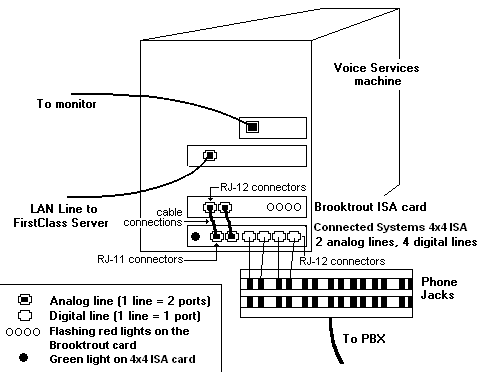
The Connected Systems PBXLink ISA 4x4 is an ISA card installed in a slot in the Voice Services machine. One card supports one four-port Brooktrout card. It connects to the PBX by digital lines (up to four) and to Voice Services by an RS-232 link. It then links to the Brooktrout card by one to two analog lines (one line supports up to 2 ports).
The following diagram is a representation of a Voice Services machine configured with 1 Brooktrout card (ISA version) and a Connected Systems PBXLink ISA 4x4:
Connected Systems PBXLink DMI-4
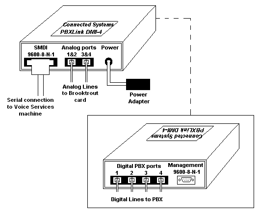
The Connected Systems PBXLink DMI-4 is an external box that provides the same function as the Connected Systems PBXLink ISA 4x4 card.
Since Voice Services uses SMDI integration, it is necessary to turn off inband tones. This is done via the serial port menus by choosing Advanced > Inband Tones and changing Suppress Tones to ON.
The DMI-4 works with both the ISA and PCI Brooktrout cards. If a Brooktrout ISA card is used, the cables that are shipped with the product are used to connect to the Brooktrout card, as illustrated below:
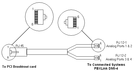
If a Brooktrout PCI card is used, you need a custom cable. Centrinity can supply this cable or one can be made following the diagram below:
Use the following connections:
RJ45 RJ12
Pin 1 Pin4 of RJ12-2
Pin 2 Pin 3 of RJ12-2
Pin 3 Pin 2 of RJ12-1
Pin4 Pin 3 of RJ12-1
Pin 5 Pin 4 of RJ12-1
Pin 6 Pin 5 of RJ12-1
Pin 7 Pin 5 of RJ12-2
Pin 8 Pin 2 of RJ12-2
Configuring the PBX
Read the Connected Systems documentation and follow all the steps for preparing and programming your Nortel Norstar PBX.
Note
The following section should be used as a supplement to the Connected Systems documentation, highlighting steps which are unique to Voice Services, or where special attention should be taken to ensure successful configuration.
The Nortel Norstar configuration is dependent upon the system arrangements you prefer. The three possible arrangements are:
• automated attendant An automated attendant answers all incoming external calls
• human receptionist A human receptionist answers all incoming external calls
• no central incoming handling There is no centralized handling of incoming external calls
Regardless of the configuration you choose, ensure that the name table is completed in its entirety and that all entries are correct. If this is not done, Voice Services cannot process calls and messages.
Automated attendant
In a system with an automated attendant, the system must "see" incoming external calls as soon as they ring so that it can answer them and play an appropriate greeting to the caller. In this scenario, users’ phones typically do not ring for incoming external calls, but the trunks may be assigned to buttons on the phone if desired. Note the following:
• the extension number of the first port is the pilot number that users call to access their voice messages
• the first port must have the external trunk lines assigned and ringing
• the remaining ports must not have external lines ringing
• the first port must forward-on-busy to the second, the second to the third, and so on; the last port can forward-on-busy to a human attendant or back to the first port
• users' phones should forward-on-busy and forward-on-no-answer to the prime number.
Human receptionist
In a system with a human receptionist, the system does not automatically answer incoming external calls unless they have been ringing for some time. Users' phones typically do not ring for incoming external calls, but the trunks may be assigned to buttons on the phone. Note the following:
• the extension number of the first port is the prime number that users call to access their voice messages
• external trunks must not ring any of the ports
• the first port must forward-on-busy to the second, the second to the third, and so on; the last port can forward-on-busy to a human attendant or back to the first port
• users' phones should forward-on-busy and forward-on-no-answer to the prime number
• to cause the system to answer incoming external calls that have been ringing for some time, the receptionist's phone should be set to forward-on-no-answer to the prime number.
No centralized answering of external calls
In smaller installations, there is no automated attendant and no receptionist. Instead, most or all users’ phones ring when there is an incoming external call. Note the following:
• the extension number of the first port is the prime number that users call to access their voice messages
• external trunks must not ring any of the ports
• the first port must forward-on-busy to the second, the second to the third, and so on; the last port can forward-on-busy to a human attendant or back to the first port
• users' phones can forward-on-no-answer to the prime number
• for the system to answer incoming external calls that have been ringing for some time, one phone should be set to forward-on-no-answer to the prime number after a specified number of rings. This number should be less than that used for other users' rings.
Configuring the COM port in Windows NT
Once the Connected Systems PBXLink has been installed and the COM port selected for the card has been entered on your worksheet, configure the COM port in your Windows NT operating system on the Voice Services machine:
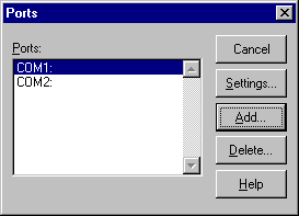
1 Open Ports from the Control Panel.
COM1 and COM2 may be preconfigured in your machine.
2 Click Add to add the COM port for the Connected Systems PBXLink.
3 Choose the COM port you configured for the Connected Systems PBXLink.
4 Set Base I/O Port Address to the number you entered on your worksheet.
5 Set the IRQ to the number you entered on your worksheet.
6 Click OK to return to the Ports dialog box.
7 Click Settings and choose the options shown on the screen below:
8 Click Advanced.
9 Ensure:
• the COM port is correct (from the worksheet as above).
• The Base I/O Port Address and Interrupt Request Line (IRQ) are set to Default.
• FIFO Enabled is selected.
10 Click OK and exit, saving all changes.
Configuring the Connected Systems PBXLink settings
Once the Connected Systems PBXLink has been connected, and the COM port has been configured in Windows NT, you have to configure the internal settings for your Connected Systems PBXLink configuration.
Create a HyperTerminal file
Create a HyperTerminal file on the Voice Services machine to initialize the Connected Systems PBXLink.
1 Choose Programs > Accessories > Hyperterminal > HyperTerminal from the Start menu.
2 Enter Connected Systems PBXLink at Enter a name for the new connection.
3 Click OK.
4 Enter the COM port number configured for the Connected Systems PBXLink, configured in NT, and recorded on the worksheet at Connect using.
5 Click OK.
6 Type m and press Enter to access the Connected Systems PBXLink menu.
7 Stop the integration before changing any Connected Systems PBXLink settings:
• Press 1 for the Configuration menu.
• Press 1 to stop the integration.
8 Enter the following settings by following the steps in the Connected Systems PBXLink manual:
PBX Type
Do not choose a PBX type.
PBX Options
Prime # Enter the pilot number. If you ever change the pilot number, restart the Voice Services machine.
Number of lines licensed
Enter number of lines licensed (4, 8, 12, ... up to 24).
Connect using
COM# (where # is the COM port selected on the Connected Systems PBXLink)
Baud rate
9600
Data Bits
8
Parity
No
Stop Bits
1
9 Set the SMDI options.
Check CPID Length (option 2). This is the local dialing number length. If you live in an area where all local calls are 10 digits, ensure CPID Length is set to 10.
10 Restart the integration.
11 Type q and press Enter to exit.
12 Restart the Voice Services machine.
Troubleshooting the Connected Systems PBXLink
When the computer restarts, check the green light on the Connected Systems PBXLink:
The light is on steady
The connection was successful.
The light is on but blinks off briefly every 2 seconds
The digital line is working correctly but the integration must be restarted.
The light is off
The Connected Systems PBXLink is in boot-loader state or is not working correctly. See the Calista documentation.
The light is flashing slowly
The digital line is active but the PBX is not responding to the Connected Systems PBXLink.
The light is flashing quickly
No signal has been detected from the digital line. Check the physical connections and then check the line.
Installing the Brooktrout card(s)
Insert the Brooktrout card(s) into the slot(s) in the Voice Services machine as explained in the Brooktrout installation manual.
Install the Brooktrout software
1 Download the required Brooktrout software from the Voice Services CD.
There are three folders the Brooktrout driver requires:
• Install
• Kernel
• User.
2 Run Install.exe to install the Brooktrout driver.
3 Enter the number of lines you are installing (4 per card).
Configuring PCI Brooktrout card(s)
1 Enter the following information when prompted:
IRQ -1
DMA -1
Start faxinit on startup yes
Additional parameters required? no
2 Go to Faxinit.
Configuring ISA Brooktrout card(s)
Use defaults unless otherwise specified:
IRQ
5 (recommended)
Any available number between 1 and 10 can be used. For multi-card installations, use the same IRQ number for all cards. Remember to enter this number on the worksheet for future reference.
Set Base I/O address
• For a one-card system, the base I/O address should be 260.
• For a two-card system, the base I/O addresses should be 260 and 280.
• For additional cards, see the chart in the Brooktrout manual.
Ensure the Base I/O address is entered on the worksheet.
DMA
1 (recommended)
Kernel buffer size
8092 (default)
Kernel IRZ size
10 (default)
Enable default?
No
Start driver automatically?
Yes (default)
Load faxinit on startup?
Yes
Additiional parameters file
Enter the full path to the address file.
Example: c:\winnt\bfax\address
Address file (ISA card only)
Create the address file:
1 Create a new text (ASCII) file using Notepad.
For a one-card system with a starting I/O of 260, the file will contain one line only:
addrs 264 4
For a two-card system with starting I/Os of 260 and 280, the file will contain two lines:
addrs 264 4
addrs 284 4
2 Save the file with the exact full path you specified above.
3 Open Windows Explorer and delete the .txt extension.
Faxinit
When installation is complete, ensure the following files are in your hard disk in the directory c:\winnt\bfax\:
• bfax.sys
• faxinit.exe
• runfaxin.exe.
After faxinit.exe runs, a log file will be created called faxinit.log. Details about faxinit.log are described in Verify hardware install.
At this point, there should be no lights lit on the Brooktrout cards. Once Voice Services has started and the software configurations have been set by following instructions in the administrator's online help, the lights on the Brooktrout cards should flash randomly.
|


